
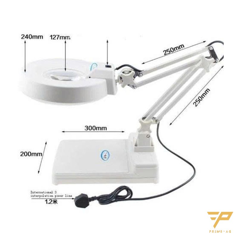
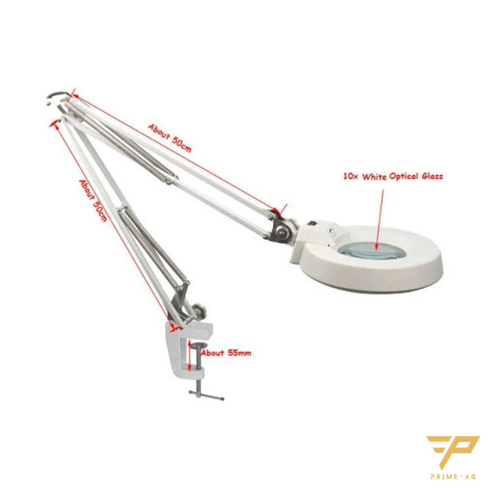
Which magnifier is best for hours of solder joint inspection in an electronics factory in Vietnam? Use a clamp-on bench magnifier with LED light: 5D (2.25×) for general visual inspection, 8D (3×) for small solder joints. When you need a stable magnification above about 10× to inspect IC leads or cracks, switch to a 7–45× stereo microscope. PRIMEAG supplies both groups.
At visual inspection stations after hand soldering, wave soldering or rework, QC staff often get eye strain after 2–3 hours, let solder bridges and insufficient solder slip through, and two inspectors checking the same board reach two different results. The main causes lie in the optical tools and the viewing conditions.
- 5D–8D lighted magnifiers for continuous visual inspection over many hours.
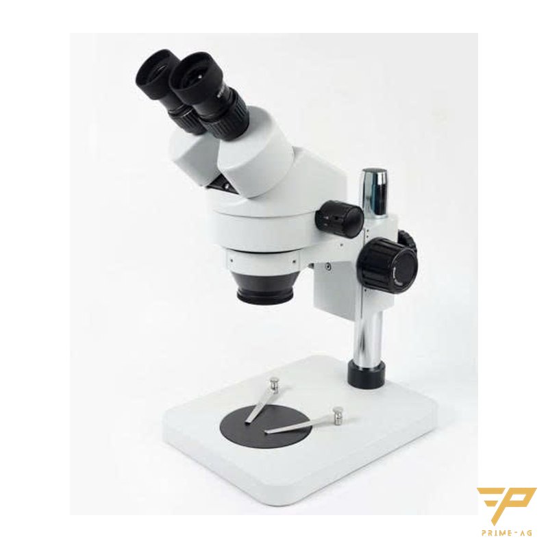
- Stereo microscopes when you need above about 10×: fine-pitch IC leads, cracks in solder fillets.
- Glare-free lighting and correct posture matter as much as magnification.
- Reference defect samples at the bench help all QC staff judge the same way.
Why the wrong solder inspection magnifier makes QC miss defects
- Wrong magnification: too weak and cracks are missed; a single-lens magnifier that is too strong gives a narrow field of view and distorted edges.
- Insufficient light or glare: shiny solder joints reflect ceiling lights as white spots.
- Distance and posture: leaning close to the board with the neck bent, judgment gets worse toward the end of the shift.
- No reference samples: each person sets their own “pass” threshold.
1. Understanding diopters and magnification
The “D” (diopter) number is the optical power of the lens, not the magnification factor. Nominal magnification is calculated with the formula M = D/4 + 1, based on a conventional viewing distance of 25 cm.
| Diopter | Nominal magnification | Suitable for |
|---|---|---|
| 3D | 1.75× | Reading labels, long-duration visual inspection |
| 5D | 2.25× | Visual inspection, assembly over many hours |
| 8D | 3× | Inspecting small solder joints |
Actual magnification also depends on where the lens is positioned and on the user’s eyes.
2. When to switch to a stereo microscope
The stronger a single-lens magnifier, the narrower the field of view and the more distorted the edges. When inspection consistently needs above about 10×, such as checking IC leads or looking for cracks in solder fillets, use a 7–45× stereo microscope and clamp-on bench magnifier. The binocular image has depth, making it easier to tell convex and concave joints apart from reflections.
IPC-A-610 specifies inspection magnification according to land width or component lead width; check the edition your factory uses before deciding on tools.
3. Lighting and posture at the inspection station
The LED light on the magnifier illuminates the viewing area directly and reduces shadows. If there is still glare, change the lens angle. If the bench lacks ambient light, add a desk lamp for the inspection station; see desk lamps and rack-mounted LED lights for workstations.
Use the folding arm to bring the lens in front of the face, so the inspector sits with a straight back and rests their hands on the bench while turning the board.
4. Reference defect samples and eye-rest rotation
Post a board of pass and fail sample photos right at the bench: solder bridges, insufficient solder, cracked joints, solder balls. Inspectors compare directly instead of relying on memory. Rotate optical inspection with other tasks so eyes can rest.
If defects keep recurring, review the soldering process: choosing soldering tips, setting temperature and storing solder paste; rework supplies: soldering tips, soldering irons, solder and soldering accessories.
Choose tools by task
| Inspection task | Tool |
|---|---|
| General visual inspection after wave soldering, full-shift inspection | 5D clamp-on bench magnifier with LED light |
| Small component solder joints, after rework | 8D clamp-on bench magnifier with LED light |
| IC leads, cracks, needing above about 10× | 7–45× stereo microscope |
Inspection station self-check
- Does the lens diopter match the size of the joints being inspected?
- Do inspectors have to bend their neck to see?
- Is the defect sample board within their line of sight?
Frequently asked questions
- Is an 8D magnifier better than 5D for all solder inspection? — No. 8D (3×) suits small solder joints but has a narrower field of view; for continuous visual inspection over a full shift, 5D (2.25×) causes less eye strain.
- Does every inspection bench need a stereo microscope? — Not necessary. A stereo microscope is slower when scanning a whole board; place it at re-inspection or rework stations, and use lighted magnifiers on general inspection benches.
- How do I choose magnification for solder joint inspection? — Follow the assembly acceptance standard your factory applies, usually IPC-A-610; it links magnification to land and component lead size.
Email: info@primeag.vn · Phone/Zalo: +84 906 108 292
Written by the PRIMEAG engineering team
Updated: 2026-10-28